WS2812B LEDs on the TM4C123: hardware PWM instead of bit-banging
I spent the first stretch of the year on Israel Gbati’s Bare-Metal Embedded C Programming on the STM32 (the earlier stm32 posts). Recently I switched boards to pick up Jonathan Valvano’s Introduction to the ARM Cortex-M Microcontrollers alongside Miro Samek’s Quantum Leaps material. Both are built around the TM4C123GH6PM LaunchPad (the TI Tiva C board), so the TM4C is now the desk fixture instead of the Nucleo.
The first thing I wanted to do that neither course walks through directly was drive a strip of WS2812B addressable RGB LEDs, the NeoPixel-style parts where a single data pin controls a whole daisy chain. It turned into a good excuse to learn the TM4C’s PWM peripheral properly, and to find out how many ways there are to get one register wrong.
What the WS2812B actually wants
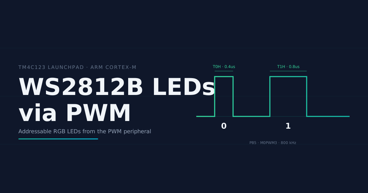
Each LED expects 24 bits in GRB order (green, red, blue), most-significant bit first. The hard part is the physical layer: bits are encoded as pulse widths on the data line at roughly 800 kHz.
| quantity | target | allowed range |
|---|---|---|
| bit period | 1.25 us | +/- 600 ns |
| ‘0’ high time (T0H) | 0.40 us | 0.25-0.55 us |
| ‘1’ high time (T1H) | 0.80 us | 0.65-0.95 us |
| reset (line low) | > 50 us | - |
A ‘0’ is a short pulse, a ‘1’ is a long pulse, and the difference between them is 400 ns. The +/-150 ns tolerance is painful to hit from C. I tried bit-banging it first, toggling a GPIO in a tight loop with cycle-counted delays, and it was as fragile as you would expect: a single extra instruction or a different optimization level and the pulse widths drift, a ‘0’ starts reading as a ‘1’, and the LEDs show the wrong color or nothing at all. The right tool is the hardware PWM peripheral, which generates the carrier in silicon and leaves the CPU to decide only which pulse width to emit for each bit.
The TM4C PWM peripheral
The TM4C has two PWM modules. Each has four generator blocks, and every generator is a 16-bit down-counter plus two comparators (A and B) that produces two output pins (pwmA and pwmB). I used module 0, generator 1, output B, which is routed to PB5 as the signal M0PWM3.
Three ideas make the whole thing click:
- LOAD is the value the counter counts down from. It sets the period: period =
(LOAD + 1)clock ticks. - CMPB is a compare value. When the counter descends through it, the generator raises an event.
- GENB is the output’s program: for each event, what should the pin do? The actions are drive low, drive high, invert, or do nothing.
I wanted each bit period to start low, then go high, with the high time equal to CMPB (so I can set the duty per bit). That means drive low when the counter reloads to LOAD, and drive high when it crosses CMPB on the way down. To keep the register readable I built small macros for each event field instead of a magic hex constant:
#define PWM_DRIVE(ACT, REG)        ((ACT) << (REG))
#define PWM_ACT_LOAD(ACT)          PWM_DRIVE(ACT, 2)    /* bits [3:2]   */
#define PWM_ACT_COMPB_DOWN(ACT)    PWM_DRIVE(ACT, 10)   /* bits [11:10] */

#define PWM_LOW  2U
#define PWM_HIGH 3U

PWM0->_1_GENB = PWM_ACT_LOAD(PWM_LOW) | PWM_ACT_COMPB_DOWN(PWM_HIGH);
That one line is the entire waveform shape. The shift amounts (2 and 10) matter more than they look, which I learned the hard way.
With the system clock at 80 MHz the timing falls straight out of SystemCoreClock:
#define PWM_LOAD (SystemCoreClock / 800000U - 1)   /* 1.25 us period -> 99  */
#define CMPB_T0  (SystemCoreClock / 2500000U)      /* '0' -> 32 ticks, ~0.40 us */
#define CMPB_T1  (SystemCoreClock / 1250000U)      /* '1' -> 64 ticks, ~0.80 us */
Both values land dead center in the WS2812B’s allowed ranges.
Streaming without interrupts or DMA
The interesting part is how you feed 24 compare values (or 192, for a chain of eight LEDs) to the generator, one per 1.25 us bit period, without an interrupt.
The trick hinges on a detail of the TM4C compare registers: writes to CMPB are locally synchronized. A value written during period P does not take effect until the counter next hits zero, so it becomes active in period P+1. That sounds annoying but it is exactly what removes the timing race. You write each bit one period ahead and pace yourself by polling the raw counter-zero status flag. No NVIC interrupt is needed, which matters here because this board’s startup vector table has the PWM interrupt slots left as zeroed Reserved entries, so enabling the IRQ would just fault:
static void waitPeriod(void) {
    while ((PWM0->_1_RIS & BIT(0)) == 0) { }   /* raw "counter hit 0" flag */
    PWM0->_1_ISC = BIT(0);                      /* clear it for next period */
}
The streamer is then a small pipeline: warm up for one period with the output off, pre-load bit 0, turn the output on, and from there just write the next bit and wait:
PWM0->_1_CMPB = ((bytes[0] >> 7) & 1) ? CMPB_T1 : CMPB_T0;  /* bit 0 = MSB of byte 0 */
waitPeriod();
PWM0->ENABLE |= BIT(3);                                       /* let the signal out */

for (int i = 1; i < nbits; i++) {
    int byte = i / 8;                                          /* which byte */
    int bit  = 7 - (i % 8);                                    /* MSB-first */
    PWM0->_1_CMPB = ((bytes[byte] >> bit) & 1) ? CMPB_T1 : CMPB_T0;
    waitPeriod();
}
waitPeriod();   /* let the final bit play out */
The i / 8 and 7 - (i % 8) are the bit math: walk a single counter across the whole stream and derive which byte it lives in and which bit inside that byte. The same loop scales from one LED (24 bits) to a chain of eight (192 bits) with no code change.
Three bugs
The driver is small. Getting there was not. Three bugs stood between me and a lit LED, and each one is worth remembering.
1. The output was stuck high, no light at all. This was the GENB line. I wrote the “drive low on load” action at bit 4, on the assumption that ACTLOAD lived at bits [5:3]. It does not. ACTLOAD is at bits [3:2]; bit 4 is ACTCMPAU, a field that only fires in count-up/down mode, which I was not using. So ACTLOAD stayed at 0 (“do nothing”), the only configured action was “drive high on compare”, and the line went high on the first compare and never came back down. The WS2812B saw a constant high, which is not a valid frame, so nothing lit. The fix was reading the datasheet’s field table instead of trusting my own comment: shift by 2, not by 3. The macro version above makes that mistake structurally hard to repeat, because the field name pins the shift.
2. The board hard-faulted the instant enablePort ran, and the blinky stopped. No infinite loop anywhere in the code, just a dead board. The cause was the floating-point unit. The TM4C123 is a Cortex-M4F, so it has an FPU, but the FPU is disabled at reset and software has to turn it on (set SCB->CPACR for coprocessors CP10 and CP11) before any float instruction runs. My build uses -mfloat-abi=hard, so the duty-cycle math in the PWM init compiled to a real VFP instruction, which faulted because the FPU was still off. The startup file already had the enable code, but it was wrapped in #ifdef ENABLE_FPU, and nothing in the build defined that symbol. Adding one line to the CMake config fixed it:
target_compile_definitions(${CMAKE_PROJECT_NAME} PRIVATE ENABLE_FPU)The lesson, which I should have carried over from the printf-and-heap saga on the STM32: a “hang” with no loop in sight is almost always a HardFault. Check what the startup actually enabled before you chase logic bugs.
3. Exactly one LED lit up, ignoring the other seven. The streamer takes a bit count, but I passed a byte count: streamBits(grb, count * 3). For eight LEDs that is 24, which is one LED’s worth of bits, so the rest of the chain got nothing. The fix is count * 24. A unit mismatch between two functions in the same file is embarrassingly easy to miss when one counts bytes and the other counts bits.
What stuck
A few things I will not forget:
- The PWM generator is a tiny state machine you program with GENA and GENB. Once you stop thinking “duty cycle” and start thinking “at this event, do this to the pin”, the whole peripheral makes sense, and the same model generalizes to dead-band motor drives and everything else on the chip.
- Read the register field layout from the datasheet, every time. Bit positions are not where you remember them. ACTLOAD living at [3:2] instead of [5:3] cost me an afternoon.
- Locally-synchronized register writes are a feature, not a bug. They turn “feed 192 compare values with cycle-accurate timing” into “write the next one whenever, the hardware lines it up”. That single property is the reason a no-interrupt streamer works at all.
- A board that goes dead with no
whileloop in your code is sitting on a HardFault. Look at the startup config (FPU, vector table, stack) first.
The driver, the bit-bang version it replaced, and a longer PWM register guide I wrote up while untangling all of this live in the TM4C workspace. Next up on the board: put the ADC and the PWM together to read a knob and recolor the strip, which is shaping up to be a satisfying milestone.