STM32 bare metal hello world
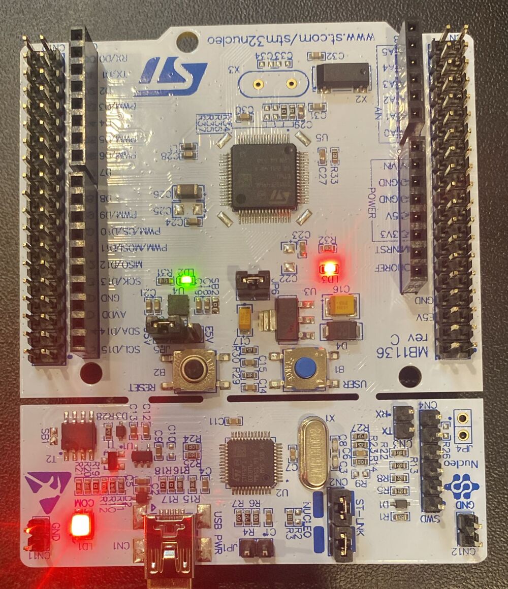
I’ve recently been working through Israel Gbati’s Bare-Metal Embedded C Programming (Packt) as my first foray into embedded systems. Chapters 1 and 2 cover getting the environment set up and understanding the hardware. By the end of Chapter 2 I had the LED on my Nucleo-F446RE actually on.

The code is unidiomatic (no HAL, no abstractions, just raw register addresses from the reference manual) but that’s the point.
#define GPIOA_BASE          0x40020000
#define RCC_BASE            0x40023800
#define RCC_AHB1ENR_OFFSET  0x30
#define GPIOAEN             0x0   /* bit 0: enables GPIOA clock */
#define GPIOx_ODR_OFFSET    0x14  /* output data register */

#define GPIOA_MODER  (* (volatile unsigned long *) (GPIOA_BASE + 0x00))
#define RCC_AHB1ENR  (* (volatile unsigned long *) (RCC_BASE + RCC_AHB1ENR_OFFSET))
#define GPIOx_ODR    (* (volatile unsigned long *) (GPIOA_BASE + GPIOx_ODR_OFFSET))

int main(void)
{
    RCC_AHB1ENR |= (1 << GPIOAEN);   /* enable GPIOA clock */

    GPIOA_MODER &= ~(0x3 << 10);     /* clear MODER5 */
    GPIOA_MODER |=  (0x1 << 10);     /* set MODER5 to general-purpose output */

    GPIOx_ODR |= (1 << 5);           /* set PA5 high, LED on */

    for (;;) {}
}
Three things are happening here:
Enable the GPIOA clock. Peripherals on STM32 are clock-gated by default to save power. Writing to
RCC_AHB1ENRturns the clock on before any GPIO register access, otherwise the writes just disappear.Configure PA5 as output.
MODERis a 2-bit-per-pin field. Bits 10-11 control pin 5. Clearing them first and then writing01sets the pin to general-purpose push-pull output.Drive the pin high. Writing bit 5 of the output data register sources current through the LED to ground.
That’s it. The follow-up post adds a toggle loop and walks through the GNU ARM toolchain manually.