
Handmade drone part 1: building the devFrame from scratch
This is the first post in a series about building a drone from the ground up for fun and learning! A 3D printed, hand-assembled, hand-wired quadcopter that I will eventually fly with ArduPilot on an STM32 and a Raspberry Pi Zero 2 W as a companion computer.
The goal is a slow-flying camera drone. Something stable enough to carry a camera, hover in place, and fly autonomous waypoints.
What I’ve been up to
It has been a while since my last post. The gap was not laziness. I got ambitious and decided to build out a proper workshop for my projects. Along the way I picked up 3D printing and learned the rudimentary basics of FreeCAD. The motivation was straightforward: I wanted to expand the scope of my embedded projects beyond dev boards and breadboards to include mechanical parts I design and fabricate myself. If I want to build enclosures, mounts, brackets, and eventually full structural parts that fit the electronics rather than the other way around, I need to be able to design and produce them myself.
This drone project is the first real test of that capability. The frame is someone else’s open source design, not mine, but I hope the process of printing it, troubleshooting the filament, and understanding why each part is shaped the way it is will teach me enough to really get started in this realm. The goal is to eventually design my own parts from scratch. This is step one.
Why build instead of buy
I’ve been working through embedded C on STM32 for the past few months, writing up bare-metal blinky guides, linker scripts, and peripheral experiments. Those posts covered the fundamentals. Now I want a project that ties it all together: MCU bringup, real-time sensor fusion, communication protocols, power management, and the satisfaction of flying something I built from filament and solder.
The devFrame project by Coby Leuschke (Open Source Hardware, CERN v2.0) is exactly what I needed. It is a parametric 3D printable quadcopter frame designed around off-the-shelf carbon fiber tubes and hardware-store fasteners. No proprietary parts, no specialty tools required. More than that, it is a simple design I could print and self-source from scratch. The project looks potentially abandoned, but it has enough well-documented material for me to learn from. Out of everything I could find, it was the closest thing to a zero-to-hero guide and design that I could follow with no prior experience in drone construction.
What the devFrame gives you
The design is meant to support Stretch X, Hybrid X, and H configurations plus a skid-steer rover variant. As of now, only the Stretch X quad build is documented. That is the one I am building.
Key specs:
- 300-500mm frame size
- Prop sizes from 5” to 10”
- Up to 2kg flying weight
- 10mm tube mounts on 60mm spacing for off-the-shelf accessories
- 15mm and 30mm mounting hole spacing for flight controllers and companion computers
- Mounts for Raspberry Pi (0/3/4), GPS modules, flow sensors, and rangefinders
The large internal volume is what sold me. I need room for an STM32 flight controller, a Pi Zero 2 W companion computer, a GPS module, and a camera. I’m not building something to race. I’m building it with 10-inch props for slow, efficient flight. The kind of flight style where endurance and stability matter more than speed and agility. At the end I have many people in my life who would appreciate access to a camera drone, so it will have interesting utility beyond being a learning project.
Printing the parts
Filament choice was simple for me. I settled on 3D-Fuel’s PCTG Pro. The deciding factors were low odor and low fumes during printing. I have a Sovol Zero printer that can handle advanced filaments like nylon-carbon fiber, but I don’t have a ventilated workspace, abrasion-resistant nozzles, or any real reason to spend that kind of money on a first build that might not fly. The plan is to validate the airframe with PCTG first, then do a v2 rebuild in nylon-CF or PC-CF once I’ve built out my printing workspace with proper fume extraction and HEPA filtration.
Dialing in PCTG Pro was a pain. It is stringy by nature and overhangs printed badly until I found the right cooling profile. What finally worked was very conservative part cooling across the board, except on bridges and overhangs where I cranked the fan up to 70%. I had to reprint the base frame parts at least twice before I was happy with the settings. My settled nozzle temperature was 255°C.
I printed everything in the base frame set: the main structural joints, arm clamps, motor mounts. All of it came out usable at 255°C. Then I moved on to the electronics mounts and got ambitious. I bumped the temperature to 265°C to see if slightly hotter extrusion would improve layer adhesion on the smaller, more detailed parts. It did not. Instead, PCTG carbonized inside the heatbreak and created a hard obstruction that I could not clear. A catastrophic heatbreak clog. I had to fully disassemble the printer head and I am now waiting on a replacement heatbreak set from Aliexpress.
I also ordered a Diamondback nozzle. The idea is that better thermal conductivity means I can print effectively at higher throughput without cranking the temperature as aggressively. A smoother nozzle exit probably would have helped prevent the carbonization buildup too. Lesson learned: be very careful when experimenting with higher print temps and clean your nozzles frequently.
Base frame assembly
Despite the printing setbacks, I had all the structural parts I needed to assemble the base frame. The devFrame uses off-the-shelf carbon fiber tubes held in place by the printed clamps and joints, secured with standard hardware-store fasteners. The assembly itself is straightforward: cut the tubes to length, press the printed joints onto the tube ends, and bolt everything together.
The base frame is complete. Here it is assembled on my bench:
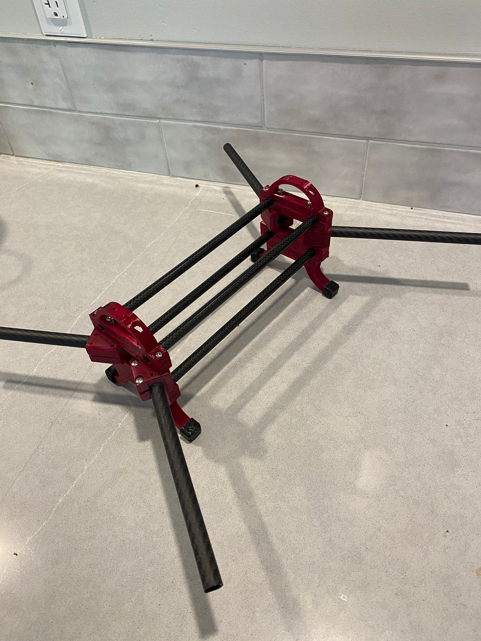
The electronics mounts will come once the printer is back in action. For now the structure is solid, the geometry is true, and I have a platform to start planning power distribution and motor placement.
What’s next
The frame is built. The next steps in this series:
- Part 2: Power distribution, motors, and ESCs. Wiring the propulsion system and doing initial bench tests.
- Part 3: Flight controller bringup. Getting ArduPilot running on an STM32, initial calibration, and motor mapping.
- Part 4: Companion computer. Setting up the Pi Zero 2 W, MAVLink communication with the flight controller, and basic telemetry.
- Part 5: GPS, sensors, and first flight. Adding navigation hardware and taking it outside.
Each part will cover what I did, what went wrong, and what I learned.
The bigger picture
The drone is the immediate project, but it sits inside a larger plan: turning my shed into a real small-scale prototyping space. The insulation work is already in progress. Once that is done, I want to build a climate control system around an STM32, temperature and humidity sensors, solid state relays, and a ventilation system with HEPA filtration. A particulate matter sensor and a fume detection setup will monitor air quality and keep the space safe to work in, especially when printing filaments that off-gas. This is an embedded project in its own right and I will write it up when I get there.
Further out, I intend to add a Carvera CNC mill to the shop for PCB prototyping and light aluminum work. And at some point I want to build a Voron 2.4 or Trident as a proper enclosed, high-temperature printer that can handle engineering-grade filaments on a larger scale.