
Debugging My First GPIO Driver
Part 1: Setup and Debugging
Today I started working through chapter 7 of the bare metal C book. Building on the CMSIS memory-mapped hardware post and the CMake/CLion setup, I wrote my first GPIO driver. I ran into a small issue with a typo that I ended up resolving in what I believe is a real sign of growth and progress.
The first part of the work today was writing my first GPIO driver copied from the book. Gbati does provide a GitHub with all the code, but I believe typing out the code yourself is a pretty critical part of learning, so I always retype all the code from the book instead of copying and pasting. In this case retyping the code myself offered a great learning opportunity.
The code I wrote from the book is below and if you are sharp you will probably be able to spot what I did wrong right away.
gpio.c
//
// Created by magd on 2026-04-17.
//

#include "gpio.h"

#define GPIOAEN     (1U<<0)
#define LED_BS5     (1U<<5)  //Bit Set Pin 5
#define LED_BR5     (1U<<23) //Bit Reset Pin 5

void led_init(void) {
    //Enable clock access GPIOA
    RCC->AHB1ENR |= GPIOAEN;
    //Set PA5 mode to output mode
    GPIOA->MODER |= (1U<<10);
    GPIOA->MODER &=-(1<<11);
}

void led_on(void) {
    //Set PA5 High
    GPIOA->BSRR |= LED_BS5;
}

void led_off(void) {
    //Set PA5 Low
    GPIOA->BSRR |= LED_BR5;
}
main.c
/**
**************************
 * @file           : main.c
 * @author         : Magd Aref
 * @brief          : Main program body
 **************************
 */

#include "gpio.h"

int main(void)
{
    //initialize LED
    led_init();
    /* Loop forever */
    while(1){
        led_on();
        volatile int i;
        for (i = 0; i < 200000; i++) {
            __asm__ volatile ("nop");
        }
        led_off();
        for (i = 0; i < 200000; i++) {
            __asm__ volatile ("nop");
        }
    }
}
Now of course building on what I did yesterday I used CLion to flash the board directly and I instantly ran into an issue. No blinking. I decided this would be the perfect opportunity to really up my debugging skills in CLion. I went and found the .svd file for the Nucleo board so CLion could decode the peripheral registers, set a breakpoint in led_init(), and stepped through watching the GPIOA registers in the peripherals tab.
First I checked the clock. RCC->AHB1ENR showed bit 0 set, so GPIOA was enabled. Good. Then I stepped past the two MODER lines and checked GPIOA->MODER. I expected bits 10-11 to read 0b01 (general-purpose output). Here’s what I saw:
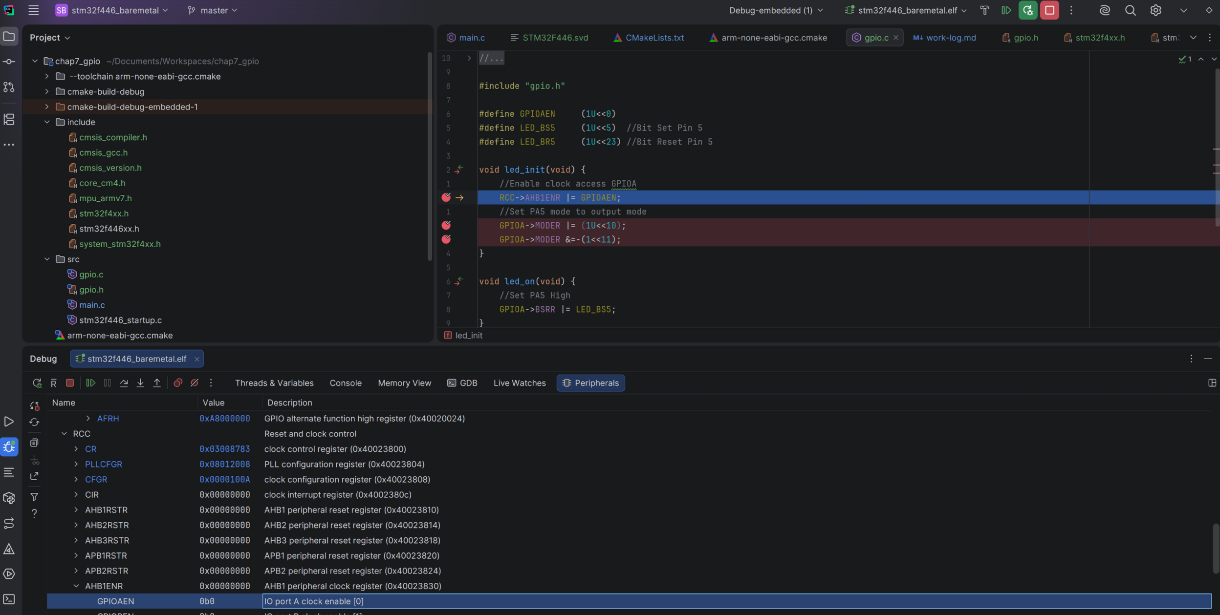
RCC clock enabled, looks good so far. But look at the next screenshot after the MODER writes.
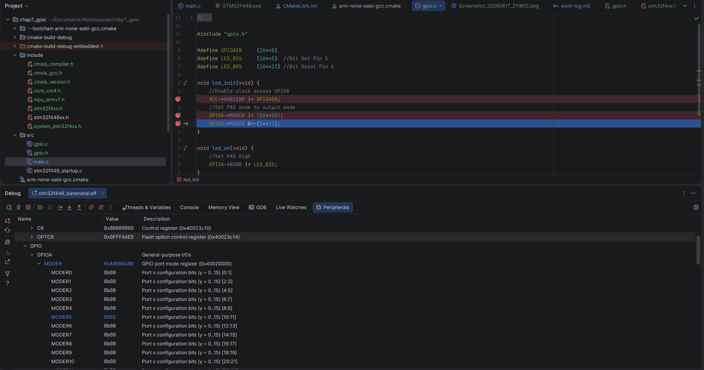
Bingo. Bits 10-11 read 0b10 instead of 0b01. Pin 5 was in alternate function mode, not output. The second MODER line failed to clear bit 11 because I mistyped GPIOA->MODER &=-(1<<11);. The correct code should be GPIOA->MODER &=~(1<<11);. I swapped the ~ for a - accidentally. One character. The bitwise NOT operator vs the negation operator. Completely different result.
Upon running again I got the LED light to turn on but not off. Again I stepped through and watched the BSRR register. The BSRR register works by writing to specific bit positions: bits 0-15 set the corresponding pin, bits 16-31 reset it. Pin 5 resets at bit position 21 (16+5). My define had (1U<<23), which was resetting pin 7 instead of pin 5. It should be (1U<<21).
After that correction the Blinky program was up and running again with the driver I wrote. This marks my first successful tiny hardware abstraction and active debugging of my board.
Part 2: Adding a Push Button
In the second part of this chapter Gbati introduces the blue push button on the Nucleo board. The button is connected to PC13 and it’s active-low, meaning it reads HIGH when not pressed and LOW when pressed. This is worth knowing because it’s counterintuitive at first. The get_btn_state() function handles this by checking if the pin is low and returning true (pressed).
I added button_init() and get_btn_state() to gpio.c, wired it into main.c, and this time things worked first try. No debugging needed. Button pressed, LED on. Button released, LED off.
Conclusions on Chapter 7
Two typos. A ~ vs - and a 23 vs 21. Both invisible in code review, both immediately obvious in the peripherals view. The GPIO driver abstraction itself is straightforward. What mattered here was learning to debug hardware by observing what the registers actually contain instead of re-reading my source code hoping to spot the mistake.
In the next chapter we will cover the SysTick timer.